
FIELD NOTES / HONEYCOMB
Honeycomb Panel Window Reveals: Coordinating the Reveal, Sill and Head
A honeycomb panel window reveal has to coordinate the panel return, the window frame, the sill and the head flashing in one tight space — and the detail only works when all four are drawn together.
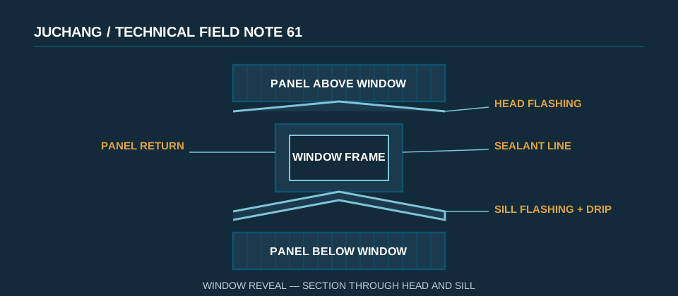
A honeycomb panel window reveal detail starts with the opening, not the panel
A honeycomb panel window reveal detail is a coordination problem before it is a panel problem. The reveal is the strip of wall between the outer face of the cladding and the window frame, and in that strip four things share the same depth: the folded return of the panel, the window frame and its fixing, the sill flashing and the head flashing. On a flat elevation each looks simple. At a real opening they compete for the same millimetres, and the detail that fails is usually the one drawn last.
Start with the opening itself. The structural opening and the finished opening are rarely the same size, and the difference is where reveal details go wrong. Ask for the window frame position in the wall depth, the tolerance on the structural opening, and the finished reveal depth the architect expects. A honeycomb panel return is made by routing and folding, so its depth is set by the blank and the fold, not by cutting on site. If the reveal depth on the drawing does not match the return depth the factory can fold, somebody has to change a drawing, a frame position or a panel size — cheapest before fabrication, not after the panels arrive.
Ownership of the interface matters as much as geometry. On most projects the window supplier owns the frame and its fixing, the cladding supplier owns the panel and its return, and the flashing sits between them, owned by whoever the specification names. A honeycomb panel window reveal detail should therefore name the owner of every line it shows. A line with no owner is a line nobody will build. Hexcel’s sandwich design guidance makes the same point in structural terms — a sandwich panel is a system of skins, core and fixings, and each load path has to be followed through to its support.
Measure before you draw the final version. Record the opening width and height at head, sill and both jambs, the squareness of the opening, and the frame position relative to the face of the cladding. Where the opening is out of square, decide on the drawing whether the panel return absorbs the difference or the frame does.
The sill: give water a way out and a reason to leave
The sill is the part of the reveal that water tests first. Rain runs down the face of the panel above the window, across the head, down the glass and the frame, and arrives at the sill looking for somewhere to go. A good sill detail gives it a fall, a drip edge and a path away from the wall. A bad one gives it a flat surface, a joint that relies on sealant alone, and a panel return sitting in the water it collects.
Draw the sill flashing with a fall away from the building and a drip that breaks the water before it can run back along the underside. The flashing should lap over the panel or the return below it, never the other way round, so water running down the face steps outward at every lap. End dams at the ends of the sill stop water tracking sideways into the jamb, where it would sit against the panel return and the frame. Where the sill meets the jamb, show the lap and the seal, not just a line on the elevation — a corner drawn as a single line will be built as a guess.
Sealant at the sill is a second line of defence, not the first. The ALUCORE processing guide calls out thermal expansion when selecting joints and fixings for outdoor use, and the same applies at a sill: the joint between the sill flashing and the frame moves with temperature, and the sealant has to be sized for it. Ask the sealant supplier for the joint width, the backing and the adhesion to the finish proposed. And confirm that the panel return below the sill is not the drainage path — if water has to cross the return to leave the building, the detail is wrong.
The head: flashing above, panel return below
The head of the window is the mirror of the sill, with the water running the other way. The panel above the window sheds water onto the head flashing, and the flashing has to throw it clear of the frame and the glass below. The most common failure at the head is not a missing flashing but one drawn too short, too flat or lapped the wrong way — water runs down the panel face, meets the head joint, and finds its way behind the flashing and into the reveal.
Show the head flashing lapping over the panel return below it and tucked behind the panel above it, with a drip at its outer edge. The drip matters more at the head than anywhere else, because the water arriving there has already travelled down the face above and carries speed. A head flashing without a drip lets water curl under its edge and run down the frame. Where it meets the jamb, close the corner on the drawing, with the lap and the seal shown, so the site team is not inventing a corner detail at height.
The panel above the window needs its own attention. Its return turns down into the reveal, and the fixing for that return competes with the head flashing for the same space. Confirm on the section that the return fixing and the head flashing can both be installed in the order the detail assumes — a fixing that can only be reached before the flashing is fitted will be fitted in the wrong order on site.
Movement is the other head question. The panel above the window and the frame below it expand at different rates and are fixed to different supports, so the head joint has to absorb differential movement. State the fixed and sliding points on the drawing and size the joint for the movement the project expects — a head joint drawn tight to the frame looks neat on the elevation and fails in the first hot season.
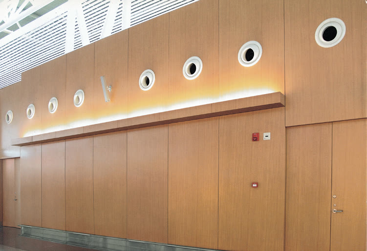
The jambs: returns, clearance and fixings competing for space
The jambs are where the reveal detail is tightest. On each side of the window the panel return, the frame, the frame fixing, the sealant joint and the panel fixing all sit within the depth of the reveal, and the drawing has to prove they fit. The return is usually the deepest item, and its depth is set by the reveal depth less the clearances the other parts need. If the return is drawn to the full reveal depth, there is no room left for the frame fixing or the sealant, and the installer will either cut the return or leave the sealant out. So the return depth must be stated on the drawing as a dimension the factory works to, with the clearances shown beside it.
Edge distance is the check that protects the panel at the jamb. A fixing or insert placed too close to the folded edge of a return can crush the core locally or split the fold. Confirm the permitted distance from fixing to panel edge for the build-up proposed, and show the fixing positions on the jamb section. The engineer should check core shear and local compression where the return is loaded — a finish sample demonstrates appearance, but it cannot replace that review.
Clearance for the window itself is easy to forget. Opening sashes, handles and blinds all need room inside the reveal, and a panel return folded too deep will foul a handle or block a sash. Check the swing and the hardware against the return depth on the section, and confirm the reveal liner — where the project uses one instead of a folded return — against the same clearances. The detail must show which one the project has chosen, with the fixing and the joint for that choice.
Finally, keep the jambs serviceable. Windows are adjusted, resealed and reglazed during the life of the building, and a reveal that can only be opened by removing a whole run of panels will not be opened at all. Where the project allows it, make the panel beside the window removable, so the window can be maintained without damaging the cladding.
What the reveal detail must show before fabrication
Before a single panel is folded, the reveal detail should be a complete drawing. Ask for a section through the head, the sill and the jamb, all at the same scale, all showing the same panel build-up, frame and flashings. A detail that shows the head at one scale and the jamb at another is hiding a clash. Each section should state the finished dimensions, the fixed and sliding points, the fixing type and edge distance, the sealant type and joint width, the flashing laps and falls, and the finish and sample reference for every visible surface.
Illustrative example only — the project values come from the project specification: take one opening and walk the dimensions through the three sections. Check that the return depth plus the frame clearance plus the sealant joint equals the reveal depth, that the sill fall is shown as a dimension rather than a note, and that the head flashing laps over the return below it by the amount the drawing states. If any check fails on paper, it will fail on site — and the cost of finding it on paper is a revised drawing, while the cost on site is a remade panel.
Record the decisions. The detail is a coordination document: the approved drawing revision, the frame position, the sample that approved the finish, and who cleared each interface. When the window supplier changes a frame section or the cladding supplier changes a fold, the detail shows what else has to change. File it with the panel schedule and the window schedule together, with matching revisions.
A honeycomb panel window reveal detail earns its place when it answers four questions without a phone call: where does the water go, where does the panel end and the window begin, how does each part move, and who owns each line. Draw the head, the sill and the jambs to answer all four, and the opening will look as good in its fifth year as it does on handover day.
Technical references
The sources describe general engineering considerations. Confirm product-specific values and project requirements with the responsible design team.