
FIELD NOTES / HONEYCOMB
Thermal Movement in Aluminum Honeycomb Facade Panels
Use a movement estimate to coordinate facade joints and ask the supplier how the proposed fixing detail accommodates travel.
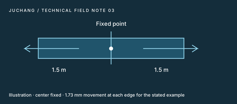
Start with the distance from the restraint
Free thermal movement can be estimated as ΔL = α × L × ΔT, where α is the applicable expansion coefficient, L is the distance from the fixed reference, and ΔT is the change in panel temperature. Use the panel system supplier’s coefficient or a value accepted by the project engineer. The ALUCORE processing guide discusses accounting for thermal expansion in outdoor joints and fixings. Its guidance is for that product and should be checked against the proposed assembly.
See what changes when the fixed point moves
For illustration, assume α = 23 × 10⁻⁶ per kelvin, a 3 m panel and a 50 K increase. The full length changes by 3.45 mm. If the fixed point is at one end, the opposite end moves about 3.45 mm under the simplified free movement assumption. If restrained at the center with sliding support elsewhere, each end is 1.5 m from the restraint and moves about 1.73 mm outward. These figures describe one panel in the stated scenario.
Estimate joint closure using both edges
A joint between two panels can close from both sides as temperature rises. The movement at each edge depends on the location of that panel’s fixed reference. The actual gap also needs to accommodate installation tolerances, support movement and the operating range of any joint component. Evaluate both hot and cold conditions from a stated installation temperature and agree on which surfaces or edges form the clear opening.
Ask for the fixing detail and movement range
Request a section that identifies fixed points, sliding points, fastener clearances and the available movement after tolerances. Coordinate intersections at corners, window perimeters and changes in support material. Provide panel temperature assumptions and the proposed joint geometry with the inquiry so the responsible project designer can assess the complete system.
Technical references
The sources describe general engineering considerations. Confirm product-specific values and project requirements with the responsible design team.