
FIELD NOTES / HONEYCOMB
Shear Transfer at Folded Returns in Honeycomb Panels
When a flat honeycomb sheet becomes a cassette, the fold at its edge does real structural work. This guide explains how honeycomb panel shear transfer at folded returns works in practice, where the bond is loaded, and what the drawing must show before the detail is approved.
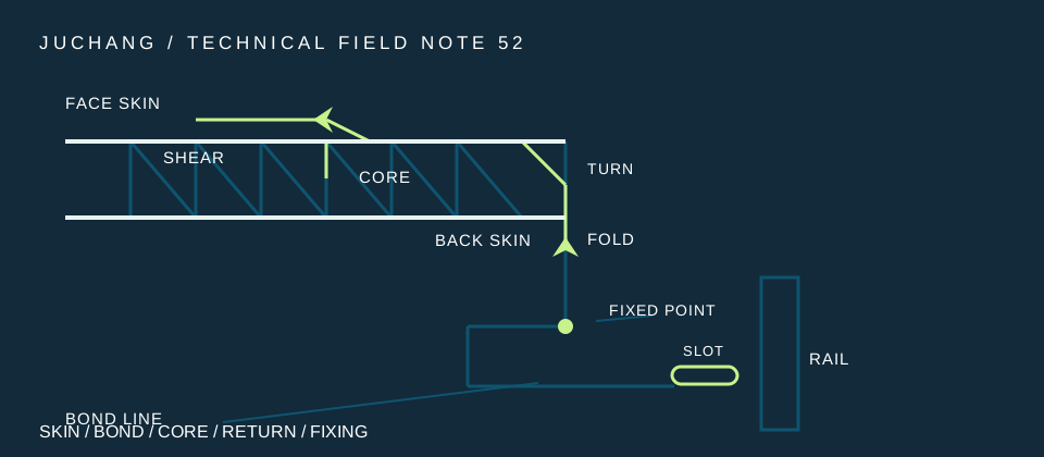
The return is part of the structure, not a trim
A cassette is a flat sandwich panel with its edges folded back to form returns, and the returns carry the fixing points that connect the panel to the rail or subframe. Wind pressure on the face skin has to reach those fixings somehow, and the only route is through the fold: from the outer skin, across the bond line into the core, through the core to the folded return, and from the return into the bracket or cleat. If any link in that chain is weak, the panel can look stiff at midspan and still fail at its edge. That is why a folded return deserves the same attention as the span between supports, and why a drawing that shows the fold as a simple right angle has not yet described the detail.
The habit to avoid is treating the return as a finishing fold — something the fabricator adds to hide the core edge. On a cassette the return is the load path. Its depth sets the lever arm between the face skin and the fixing, its fold radius sets how much the skin is worked at the bend, and its connection to the back skin or to an insert decides whether shear flows smoothly or concentrates at one line. A specifier who asks only for panel thickness and finish has not asked the questions that decide whether the edge holds.
How honeycomb panel shear transfer at folded returns actually works
Start at the face. Wind pressure pushes the outer skin, and the skin, acting as a thin plate, transfers that pressure into the core as shear. The honeycomb core is very good at carrying shear in its plane — that is the sandwich effect described in Hexcel's sandwich design guidance — but only while the bond between skin and core stays intact. At the edge of the panel the core ends, the skin turns through the fold, and the shear has to change direction: out of the plane of the face, around the bend, and into the return. The fold is therefore the point where the load path turns a corner, and corners concentrate stress.
What happens at that corner depends on three things. First, the fold radius: a tight radius works the skin harder and leaves a sharper change of direction; a generous radius spreads the turn but takes more material and more depth. Second, the bond: where the return is glued or bonded to the core edge or to a back skin, the adhesive at the fold carries shear every time the wind changes, so the bond line at the return is loaded in a way the flat field of the panel never is. Third, the fixing: a bracket screwed or riveted through the return loads the return locally, and if the fixing sits close to the fold, the local load and the turning shear add up at the same place. None of this is visible on the finished elevation, which is why it has to be settled on the drawing.
Think of it as a chain with five links — skin, bond, core, return, fixing. The drawing should let a reviewer check each link. If the drawing shows only the outside face and a fixing symbol, the chain has not been described.
What the fold does to the skin and the bond line
Folding aluminium work-hardens it. The outer fibres of the skin at the bend are stretched, the inner fibres compressed, and the material at the fold ends up harder and less ductile than the flat field. That is normal and expected, but it means the fold is not the place to put a second demand: a fixing hole drilled tight against the bend, a sharp notch, or a second fold in the opposite direction all add local stress where the material has already been worked. The drawing should keep fixings a sensible distance from the fold line and should show the fold radius the fabricator will actually use, not a nominal zero.
The bond line needs the same care. In the flat field, the adhesive between skin and core is loaded mostly in shear under bending, spread over a large area. At the return, the same adhesive — or the edge closure that replaces it — is loaded along a narrow strip, and it also has to resist the peeling action that comes from the skin trying to straighten out of the fold under load. Peel is the bond's weakest direction. So the questions to ask are concrete: is the return bonded to the core edge, is there a separate edge closure, and what evidence shows the bond holds at the fold rather than only in the flat field? A peel or shear test on a flat coupon does not answer that question on its own; the evidence should come from a specimen that includes the fold. Confirm the test scope per project — do not assume a flat-panel result covers the return.
What to check on the drawing before approval
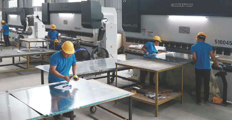
A usable return detail shows five things. Return depth and fold radius, drawn to scale, with the tolerance the fabricator will hold. The build-up at the fold: which skins are folded, whether the core is cut back, and what closes the edge. The fixing: bracket type, fastener type and size, how many fixings per return, and the distance from each fixing to the fold and to the panel corner. The movement arrangement: which fixings are fixed and which slide, and how much movement the slot allows. And the edge treatment where the return meets the next panel: the joint width, the sealant or gasket position, and the drainage path behind it. If any of these is missing, the detail is a sketch, not a coordination document.
Two checks catch most problems. First, follow the shear with a pencil from the middle of the face skin to the fixing and mark every change of direction; wherever the line turns, ask what carries it. Second, check the fixing against the fold: a fixing placed hard against the bend loads the worked material at its weakest point, while a fixing placed too far from the bend leaves a long unsupported return that can flex and work the bond loose over time. The right position is a project decision, set by the engineer with the panel build-up in front of them — it is not a value a catalogue can give. Confirm per project and per drawing.
Illustrative example only — the project values come from the project specification: take a cassette whose return is drawn deeper than its neighbour's, with the bracket moved to clear a service pipe. Tracing the load shows the shear turning through the fold and then concentrating at the single bracket, so the reviewer would ask for the bracket spacing and the pull-out evidence for that return before approving. The numbers in the example are not a recommendation; they are a way to practise the check.
What to ask the supplier before the detail is signed off
Before approving a return detail, ask for evidence that matches the detail as drawn. Pull-out evidence for the fixing as installed through the return, not through a flat sheet. Shear or bond evidence from a specimen that includes the fold. The fold radius and return depth the factory actually produces, with the tolerance it holds across a production run. And the edge closure method for the proposed build-up, with a sample that shows the finished fold. If the supplier can only offer flat-panel test data, say so plainly and ask what additional check closes the gap — a mock-up, a folded specimen test, or an engineer's review of the specific detail.
The same discipline applies to changes. A deeper return, a different fold radius, a bracket moved to clear a service, or a thinner skin all change the load path at the fold, and each one should come back through the drawing review rather than being settled on site. The fold is small — a few tens of millimetres on a panel that may be metres across — but it is where the panel meets the building. Get the return right and the rest of the cassette has something solid to hang from; leave it to assumption and the most expensive part of the facade is its edge.
Technical references
The sources describe general engineering considerations. Confirm product-specific values and project requirements with the responsible design team.