
FIELD NOTES / HONEYCOMB
Honeycomb Panel Joint Backing and Weather Seal: What Goes Behind the Joint
A honeycomb panel joint looks like a line on the elevation. Behind that line sits a small assembly of its own: a backing rod that shapes the sealant, a sealant bead that takes the movement, and a drainage path that deals with the water the sealant never sees. Get the parts behind the line right and the joint stays dry and quiet for years. Treat the line as decoration and the first leak will find the gap the drawing never showed.
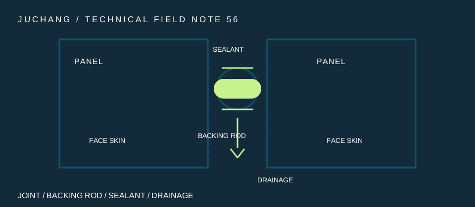
The joint is a system, not a line
A honeycomb panel joint is easy to draw and easy to get wrong. On the elevation it is a thin dark line between two panels, and on the section it is a gap of a stated width. What the elevation never shows is everything that has to work inside that gap: the backing that supports the sealant, the sealant that takes the movement, and the path that lets any water out again. A joint specified as a width alone has no weather strategy at all — it is a hope, not a detail.
Start by deciding what kind of joint the project is using. An open joint leaves a visible shadow gap and relies on the layers behind it — a drained cavity, a flashing or a secondary seal — to deal with water. A closed joint puts a sealant bead at the face and asks that bead to do the weatherproofing. Both can work, but they fail in different ways, and the drawing has to show which one it is. A closed joint without a backing rod is a bead with nothing to control its shape; an open joint without a drainage path is a gap that collects water.
The joint also has to absorb movement. Honeycomb panels expand and contract with temperature, and the fixing arrangement decides where that movement goes. The ALUCORE processing guide calls out thermal expansion when selecting joints and fixings for outdoor use: the joint width, the expected temperature range and the location of fixed and sliding points belong on the same drawing as the joint itself. A joint width copied from another project carries that project's temperature range, panel size and fixing layout with it — none of which may match this one. Confirm the joint width, the movement allowance and the fixing positions per project and per drawing.
This guide is about the honeycomb panel joint backing and weather seal detail — the parts behind the line: the backing rod, the sealant position, the drainage path and the section the fabricator needs.
The backing rod sets the sealant's shape
The backing rod is the least visible part of the joint and the one that decides whether the sealant can do its job. A sealant bead needs to bond to two faces — the two panel edges — and to nothing else. Without a backing rod behind it, the bead bonds to the back of the joint as well, and the sealant is then held on three sides. When the joint moves with temperature, a three-sided bond cannot stretch evenly; it tears at the face, and the tear is the start of a leak nobody sees until the stain appears inside.
The rod's job is to set the depth of the sealant and to keep it off the third surface. It is pushed into the joint to a stated depth, and the sealant is applied over it. The rod diameter is sized to the joint width on the sealant supplier's recommendation, and the depth is set so the bead has the thickness the supplier's joint design calls for. Confirm the figures with the sealant supplier per project and write them on the section, so the installer is not guessing on site.
Two practical points decide whether the rod works. First, it must be installed without stretching it or nicking it, because a stretched rod shrinks back and leaves the sealant too deep, and a nicked rod can let air or water through the joint. Second, it must sit at a consistent depth along the whole joint: a rod that wanders in and out gives a bead that is thick in one place and thin in the next, and the thin place is where the sealant will fail first. Corners are where backing rods are most often cut short, so the section should show how the backing continues through the corner.
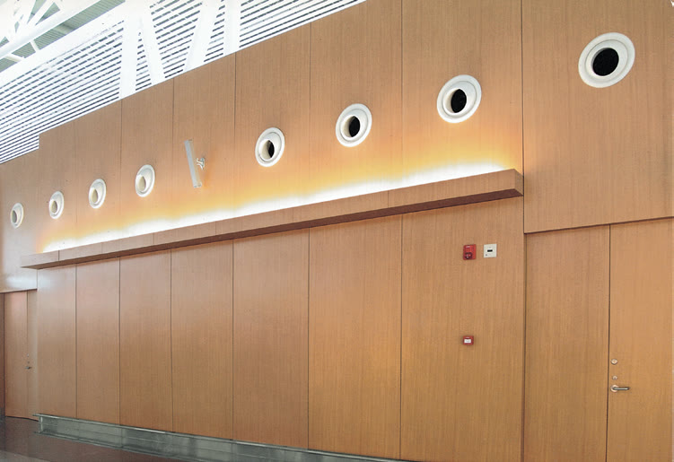
Where the sealant sits, and why depth matters
Sealant depth is not a cosmetic choice. A bead that is too deep is buried in the joint where it cannot flex, so it takes the movement as a shear at its bond lines and lets go. A bead that is too shallow is a thin skin over the backing rod, and it splits under the first season of movement. The depth the sealant supplier recommends for the joint width is the depth that lets the bead stretch and recover.
The sealant also has to be compatible with everything it touches. The panel finish, the backing rod, any primer and the sealant itself are a small chemical system, and a mismatch shows up as a bond that never forms or a bead that discolours. Ask the sealant supplier to confirm compatibility with the proposed finish and backing material for this project, and ask for the confirmation in writing with the joint design.
Some projects use a two-stage seal instead of a single bead at the face: an outer weather seal that sheds water and an inner air seal that stops air and the water the outer seal lets past. The two seals sit at different depths, each with its own backing, and the space between them is drained. A two-stage seal costs more joint depth and more care on site, but it gives the joint a second line of defence where a single bead has none. Whether the project needs one stage or two is a design decision — it belongs in the specification, with the evidence for the choice. Sealant also needs time and weather to cure: a bead applied in rain, on a wet joint, or below the temperature the supplier allows will not bond properly, and the failure will look like a bad sealant when it was a bad day to seal.
Drainage: the water the sealant never sees
No face seal lasts forever. Sealant ages, joints move, and a bead that was perfect on handover will one day let a little water past. A good joint detail plans for that day. Behind the sealant, the joint should give water a way out and a way down: a drained cavity behind the panel field, a clear path to the bottom of the joint, and an exit at the base or at a flashing that takes the water outside.
The drainage path has to be continuous to work. A cavity that is blocked by insulation squeezed into the joint, by sealant that has oozed past the backing rod, or by a flashing that was never cut to let water through is not a drained cavity — it is a tray. The section should show the path from the joint to the outside without a break, and the installer should be able to point to it on the drawing.
Heads and sills deserve the same attention as the vertical joints. Water runs down a facade and collects at every horizontal interruption, so the head flashing above a joint and the sill flashing below it are part of the joint detail, not separate items. The flashing should throw water clear of the joint below it and drain outward, not back into the panel. Where a panel return competes with a flashing for the same space, the section has to resolve the conflict before fabrication. The drainage exits should also stay visible after installation: a weep sealed over by a well-meaning installer is worse than no weep at all, because it hides the fact that the water has nowhere to go.
What the section must show before fabrication
A joint detail earns its place on the drawing when a fabricator can build from it and an installer can check against it. The section should show, at a minimum: the joint width and its tolerance; the backing rod type and the depth it is set to; the sealant type, its depth and the faces it bonds to; the drainage path from the joint to the outside; the head and sill flashings where the joint meets them; the edge closure of the panel; and the fixed and sliding points that decide where the movement goes.
The section should also name who supplies what. The backing rod, the sealant, the primer and the flashing may come from different suppliers, and each one needs to know the joint it is going into. Send the section to the sealant supplier with the joint widths and the movement, and ask for the joint design back in writing before the panels are ordered.
Illustrative example only — the project values come from the project specification: consider an elevation where the design team freezes the panel module before the joint widths are decided, and the joint at the corner ends up narrower than the sealant supplier's minimum for that movement. The choice is to change the module, change the joint, or accept a sealant that cannot move enough. Confirm the joint widths and the sealant design before the module is frozen, not after the panels are in production.
A mock-up joint, built on the actual panel build-up and sealed by the actual installer, settles more arguments than a page of notes. It proves the backing depth, the bead shape, the corner turn and the drainage path in one piece, and it gives the site team a reference to check against. The joint is the smallest part of a honeycomb panel facade and the one most likely to be left to chance. Give it a backing, a sealant position, a drainage path and a section that shows all three, and the line on the elevation will stay what it looks like: a quiet, dry gap between two panels that were meant to sit there.
Technical references
The sources describe general engineering considerations. Confirm product-specific values and project requirements with the responsible design team.